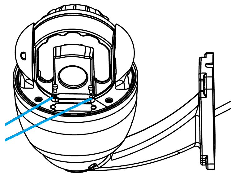
1. Unscrew the transparent DIP switch cover using a PH1 screwdriver.
Adjust the DIP switches if required (see Address ID & Baud Rate for more information, on the following pages)
Re-install the transparent cover once the DIP switches have been set.
|
|
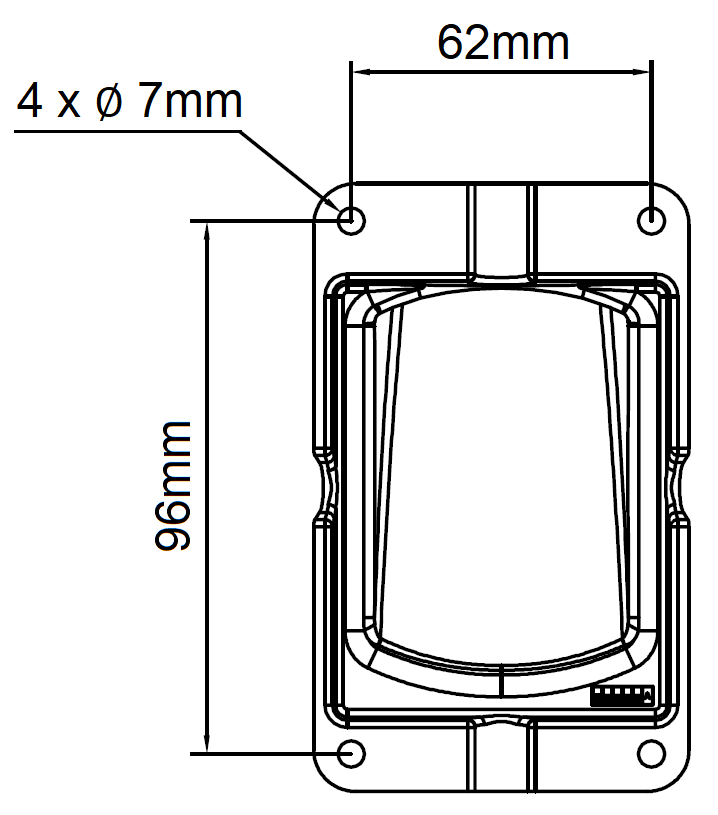
2. Mark the hole positions using the mounting bracket or using the measurements on the diagram to the right.
Drill the holes and install the wall plugs.
|
 |
3. Feed the PTZ cable loom through the bracket, then secure using the short screws provided.
|
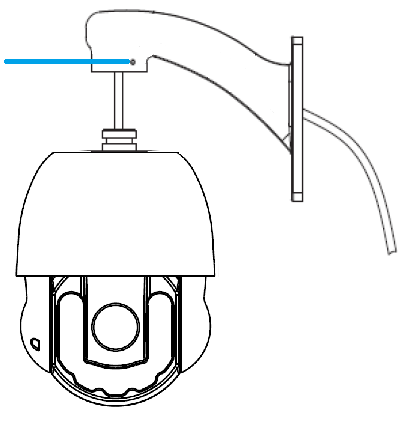 |
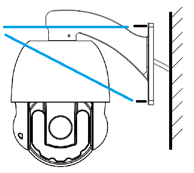
4. Connect cables for power, video (and RS485 if required) then fit the PTZ to the wall using the screws provided.
Use silicon sealant around the base, where the cable enters the bracket and in the entry cut out which is not used. The connections for the camera need to be installed in a waterproof box or similar.
|
 |
5. Remove protective film from PTZ. |
|