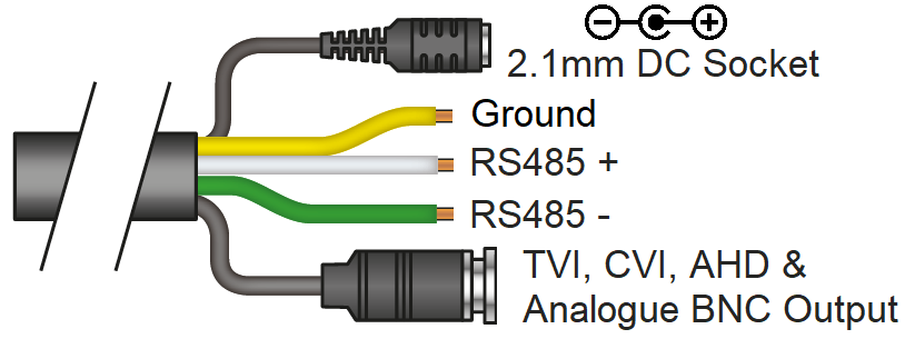
•2.1mm DC Socket - The camera has a 2.1mm socket. A 12V 2A Power supply is provided which each PTZ. If the PTZ is not being used with the provided power adaptor then ensure the power supply is regulated and rated above the current draw of the camera. The camera is polarity sensitive so connections must be correctly made.
•TVI, CVI, AHD & Analogue BNC Output - The camera has a standard BNC connector for video output, the output can be changed to AHD, CVI or CVBS if required, see 4-in-1 Technology.
•Ground, RS485 +VE / -VE - When using a PTZ keyboard or if the install requires RS485 communication then use these wires. see RS485 Wiring.
ZIP SUPA and XTRA recorders have "Coaxitron" so the RS485 cables may not be required (depending on your install).
After turning on the PTZ it will automatically start to pan and tilt as it preforms a self-test. The self-test will check all functions are working as they should be.
Powering
It is recommended to power locally, however another way to power the PTZs is using our COMPOSITE VIDEO cable (or shotgun as its also known) as this cable can carry the power to the PTZ and the video signal back to a DVR.
Do not use RG59+2 for power if run is longer than 25 metres. Either power locally at shorter distance or use a larger gauge cable.
The following shows the voltage drop for the cameras using RG59+2, IRs full on and the PTZ camera moving;
•RG59+2 run at 15 metres - voltage 11.27v DC - current 920mA
•RG59+2 run at 25 metres - voltage 10.0v DC - current 1.0A Maximum run distance
•RG59+2 run at 35 metres - voltage 9.52v DC - current 1.035A Video/telemetry issues
You can either power each PTZ with its own PSU locally to it or have the PSU’s remotely situated perhaps near the keyboard or DVR.
If RG59 + 2 cable is being used ensure the distance is no greater than 25 metres between camera and power supply. If the voltage of the PTZ drops below 10V D.C it may fail to initialise or produce intermittent video and or telemetry issues.
If distance is greater than those mentioned previously, a heavier power cable must be used to avoid voltage drop.
As voltage drops the amperage through the power supply increases which may result in damage to the power supply. As problems may occur at night when the IRs switch on, covering the IR sensor to switch on IRs during a daytime installation is recommended to test the PTZ camera before leaving site.
Video
The PTZ has a short BNC lead attached to it, this is used to carry the video to a DVR, ensure good quality RG59 coax cable or similar is used.
Note that this is a HD-TVI PTZ camera and if using RG59 this should allow a run of up to 500 metres. If you are using CAT5 then you will need HD-TVI passive baluns at both camera end and DVR end but the maximum run must not be more than 200 metres.
TIP – If there is no picture at the DVR end then use a TVI test monitor to the PTZ and check the picture quality on its own short BNC lead.