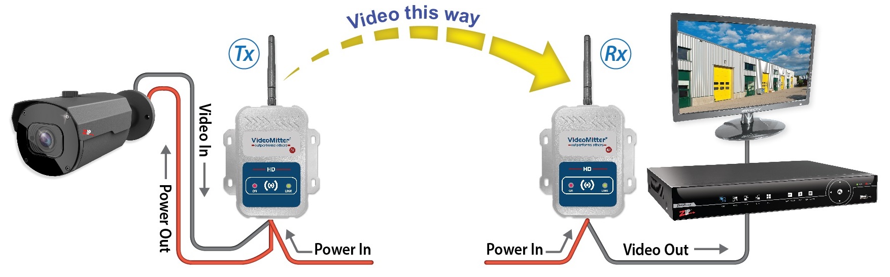
Before installation it is recommended to connect the whole transmission setup on a bench or local to the DVR / monitor. To ensure compatibility, and that all parts are in working order.
Both the transmitter and receiver require a regulated 12V DC power supply individually. When they are powered up a red power light will come on. The PSU for the receiver and transmitter needs to be capable of supplying 12V D.C. @ 190mA continuously as a minimum. (Not including the power out connection on TX for powering a camera)
|
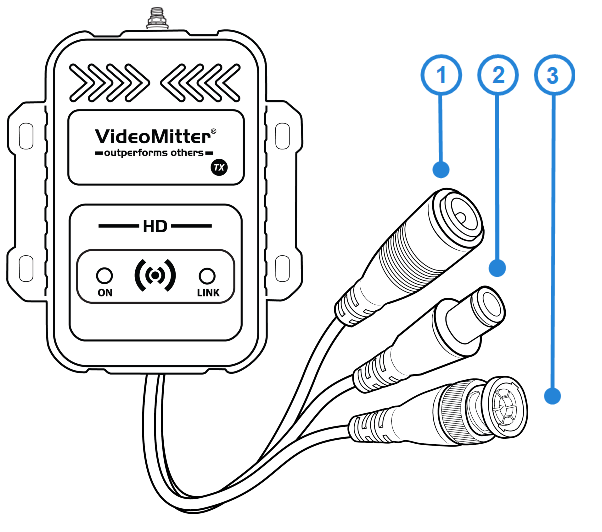
The Transmitter (TX) unit has the following connections:
1.2.1mm 12V DC Power in connection. 2.2.1mm 12V DC power out connection for power pass-through so camera and TX can share one PSU. 3.Video in connection via a BNC Lead. |
|
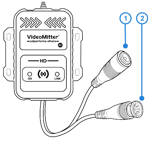
The Receiver (RX) unit has the following connections:
1.2.1mm 12V DC power in connection. 2.Video out connection via a BNC Lead. |
|
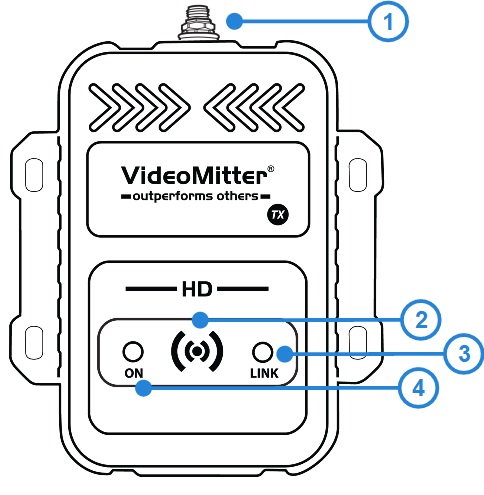
Both units have the following:
1.Antenna Connection (RP SMA Male Socket) connects to extension cables or direct connection antenna models. 2.Pair Button. 3.Green Link Indicator LED. 4.Red Power Indicator LED. |
Connecting Video
AHD 720p / AHD 1080p are the only compatible video input signals.
Connect the video input feed to the video BNC socket on the Transmitter.
Connect the video output feed to the BNC socket marked on the Receiver.
Powering a Camera
If the Transmitter (TX) power out connection for powering a camera is to be used, then ensure the PSU is rated enough to power both the MegaMitter and the camera.
For Example; most eyeball cameras on average require 750mA. Combined with the Transmitter this is roughly 950mA. Therefore a PSU rated a 12V D.C. @ 1.5A would be recommended for the Transmitter and an eyeball camera. Other cameras may require more current, so ensure the correct power rating is calculated.
To power a camera via power pass-through connect the power out cable (1) on the transmitter to your camera’s power in female lead.
Note - If you press and hold the reset button you will need to re-pair the units, see Pairing.